How to Have Family Types With Different Number of Same Item
Complex Families
File: OPE_ComplexFamilies
Objectives
- Complete the guideline of Basic Families.
- Use formulas to drive parametric values.
- Acquire how to plan a family.
- Use nested families to control the parameterisation of the family unit.
Prerequisites
- User is familiar with Revit 2015 or more recent.
- User is comfortable creating a new family from a template file.
- User is comfy using reference planes.
- User is comfortable creating basic dimensional constraints and parameters.
- User is comfy building the standard geometric forms such as extrusions, blends and sweeps.
- User is comfy adding family types and flexing the model.
Description
This guideline explains how to address the settings of circuitous Revit families, embracing the construction of a parametric skeleton, upwardly to hosted families.
Procedure
Before creating a family in Revit, specially if it is not straightforward, it is recommended that yous follow the post-obit procedure:
Planning
In order to accomplish optimal results it is recommended that you program the layout of your drawing prior to using Revit.
- Analyse the parametric behaviour of the family. Establish how the data is related.
This tin can exist achieved by sketching on newspaper.
- Secondly, in conjunction with step one, information technology is of import to collate relevant information beforehand, such equally dimensions, materials and number of family unit types. In doing and so, the family parameters and their related formulas can be clearly identified.
- Finally, information technology is important to establish if a family unit should be split into several families and understand how many families are required in order to solve the parameterisation of whatever given family.
Family Template
Before creating a new family, it is important to choose the appropriate family template. The template file is fabricated up of two basic backdrop, which are crucial during the process: category and hosting behaviour. The template too offers many less obvious settings and behaviours that can also be inherited into a family.
Table 1: summary of categories and behaviours.

Category template
When planning a family unit, it is of import to understand the settings that a template file contains. The generic model template is oftentimes chosen as a become-to choice, given that it is possible to alter the category at a subsequently stage.
Whereas this option works in nigh cases, information technology is withal, not fail-safe, and therefore information technology is non recommended as a workflow.
Family templates contain special features for each category, and determine the behaviour of each chemical element. It is for that reason that the correct family template should exist established at the kickoff. For example:
- Structural column templates have two reference levels.
- Structural beams take two location points.
In the event that one of the above categories from a generic model template needs to be changed at a later stage, their respective, special features (two reference levels, two location points) volition not be available, and as a result, the families will not behave as they should, once they are loaded into the projection model.
It is important to choose the right template from the outset in order that the subcategories which are added to "object styles" and the "cuttable" behaviour are clearly determined by the chosen category. Past changing the category, the subcategories and object mode settings will be reset.
Of course Revit does not have templates for every single category, or the detail you lot are creating might fit loosely into more than than one category. Just:
If the template for the category you need is available, choose it. There is a skilful reason for the template to exist.
If the template for the category y'all need does not be, then choose another category template, the one that best fit for the Family that yous are creating. You can modify category later.
Hosting behaviour
The hosting behaviour cannot be inverse later.
There are basically three options here: to choose the exact host you lot need (for instance "Wall based"), to choose a freestanding template (one that does not require a host) or use one of the Face-Based or Work aeroplane options. A common practice is to use Face or Work Plane Based in lieu of Wall or Ceiling based. This keeps the family more flexible and makes it less likely to become invalid should its host go missing in an update to a linked model.
Parametric Skeleton
Parameters are at the heart of a successful Revit Family unit. While you lot practice non have to make a family unit parametric, doing so volition allow for a unmarried family to be flexible plenty to address issues that otherwise may take multiple families to handle. In improver to decision-making the dimensions of an object, parameters tin can control visibility and materials, besides equally a host of other types of data, including user-defined text properties for scheduling and annotation.
Reference Planes
Define all Reference Planes needed to define the geometry. Reference Planes provide the skeleton for your family unit.
The order of creation of the reference planes is crucial. We recommend to categorize them:
- Importants
- Secondaries
- Accessories
Reference planes take a holding called "Is Reference". This holding defines the behaviour of the family when loaded into a project and you try to put a dimension or align information technology. The following options will exist available for this property:
- Strong Reference: It sets the highest priority for dimensioning and snapping. When dimensioning or snapping information technology will be highlighted commencement.
- Weak Reference: It sets the everyman priority for dimensioning and snapping. When the family is placed into the project and dimensioned, it will exist necessary pressing Tab in gild to select a weak reference, as any strong references will highlight first.
- Not a Reference: Is not visible in the project environment and cannot be dimensioned or snapped.
Some other important belongings of reference planes in families is the one "Defines Origin". It will prepare the location point of the family when placing information technology in a project. The location point is always define by two reference planes.
In Revit we cannot change the visual style of the reference planes, so we suggest to draw them with different lengths depending on the importance.
Some other trick to distinguish the importance of the reference planes is to use dimensions with different styles.

Constrain the Reference Planes
Constrain or assign parameters to the Reference Planes that you have simply created. To constraint is the state of existence restricted or bars within prescribed bounds.
Be careful and just constrain primary dimensions. Practise not create reference planes for whatsoever geometry you lot will need and practise non constrain every dimension you can, considering in that location probably will be incoherences.
Simply practise not overconstrain.

Use formulas to drive parameters
Write downward the formulas that ascertain the relation between parameters. These formulas are the cardinal of a parametric Family unit and some of them will be easy to gauge just others not and then much. Define the formulas when creating the parameters of the family types.

You can meet the syntax in the post-obit link (very useful post):
http://www.revitforum.org/tutorials-tips-tricks/1046-revit-formulas-everyday-usage.html
Provisional formulas
Provisional statement are actually useful when defining formulas for the parameters.
Conditional statement always follow the same construction in Revit:
IF (<condition>, <outcome-if-true>, <result-if-fake>)
Supported Conditional Operators:
< Less than
> Greater than
= Equal
/ Dissever
AND Both statements are true
OR 1 of the statements is truthful
NOT Statement is false
Conditional statements can contain numeric values, numeric parameter names, and Yes/No parameters, no strings allowed.
Simple IF Statement
IF (Length < 900, <true>, <false>)
Formula That Returns Strings
IF (Length < 900, "Opening besides narrow", "Opening OK")
Using logical AND
IF ( AND (x = 1 , y = 2), <true>, <false>)
Returns <true> if both x=1 and y=2, else <imitation>
Using logical OR
IF ( OR ( x = one , y = 2 ) , <true>, <false>)
Returns <truthful> if either x=i or y=ii, else <imitation>
Nested IF statements
IF ( Length < 500 , 100 , IF ( Length < 750 , 200 , IF ( Length < k , 300 , 400 ) ) )
Returns 100 if Length<500, 200 if Length<750, 300 if Length<g and 400 if Length>thou
IF with Yes/No condition
Length > 40
Returns checked box (<true>) if Lenght > 40
NOT with Yes/No condition
not(Viz)
Returns checked box (<true>) if Yes/No parameter "Viz" is unchecked, and returns unchecked box (<false>) if Yes/No parameter "Viz" is checked.
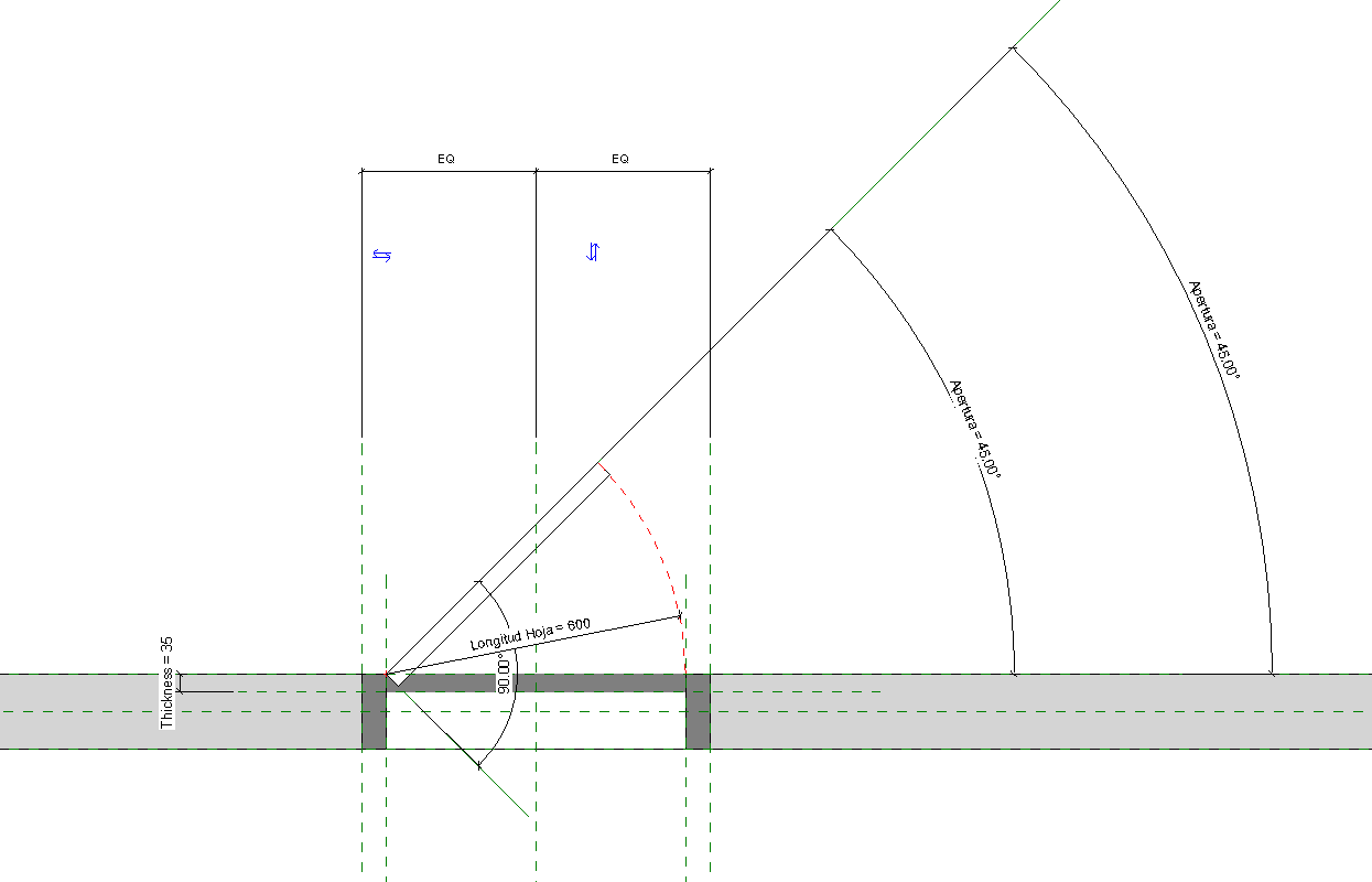
Athwart Dimensions
To control the angular dimensions of a family, employ a labelled athwart dimension to a reference line.
Unlike reference planes (with infinite extents), a reference line has specific start and end points and tin exist used to command the angular constraints within components such as a web truss, a door with an example door swing, or an elbow.
Create Bones Family Types
After the Family Template is chosen, next step proposed is to create two basic family unit types of the family. As the planning is already done, we know how many types of families we need to practise to complete the family. Nevertheless, in this step nosotros recommend just to do two basic family types. These family unit types are going to be useful for checking if the family is working appropriately during the process.
Flex the Framework
One time you have laid down your Reference Aeroplane framework and assigned parameters and constraints, test the Family by flexing it. This is washed in the Family Types dialog which you can access from the Family Types push button on the ribbon. To flex the model, simply try different values for each parameter and and so apply. If the framework moves the way yous wait, everything is expert. Otherwise, disengage and try to set up the problem.
It is much easier to fix a trouble with conflicting constraints if you know within 1 or two parameters where the problem may lie. If you wait until y'all have created and applied four or 5 parameters before you flex the family and then you take an fault, yous have a lot more possible conflicts to investigate.
3D Geometry
Geometry in Families consists of solid and void forms. Solid forms represent the actual physical parts of the Family and void forms are used to carve abroad portions of the solid forms.
For case, you could create a solid form box, and and then utilize a void class to cut a hole in it similar a donut. Both solid and void forms come in 5 varieties. These include: Extrusion, Blend, Revolve, Sweep and Swept Alloy. Using a combination of solid and void forms yous tin can create nearly whatsoever 3-dimensional shape.

Families are either cuttable or not-cuttable. If a family is cuttable, the family displays as cut when the cut plane of a program view intersects that family in all types of views. If the family unit is non-cuttable, it displays in projection, regardless of whether it is intersected by the cut aeroplane.
Nested Families
You lot can build complex forms using a combination of the solid and void forms bachelor in the Family unit Editor equally noted above. In some cases even so, managing a complex form in a unmarried Family can become cumbersome. In some cases, it makes sense to break your object into discrete parts and build the parts as separate Families. Y'all can then insert these simpler Families into another Family that represents the whole (host family). This is referred to as nested Families. When y'all manage your complex Families in this manner, you gain more command and flexibility.
Moreover, nesting helps with rotation, mirroring and arrays. If y'all need to rotate, move or mirror an element parametrically or wish to make a parametric assortment in your family, nesting is almost a must. Information technology is possible to achieve these behaviours without nesting, but it can be much more challenging.

Give careful consideration to how many levels of nesting you innovate in the model. It is possible to nest multiple layers deep. In other words, you can nest family unit A into family B and and then in plow nest family B into family C and so on. There can be benefits to doing this, but each level of nesting you innovate will increase the complexity of the terminal family unit, and will brand information technology more challenging to track downwardly bug when it does not flex properly, besides as increase the size of the family and therefore the size of the last model.
Associate Parameters
By associating family parameters, you can command the parameters of families nested within host families from within a project view. You lot tin command instance parameters or type parameters.
To associate parameters, they must be the same blazon. For example, associate a text parameter in the host family with a text parameter in the nested family.
Y'all tin can associate a host-family parameter with more than one nested family parameter of the aforementioned blazon. Besides, y'all tin associate this parameter with multiple nested families.
Shared Parameters
Shared parameters are parameter definitions that can exist used in multiple families or projects.
Shared parameter definitions are stored in a file independent of whatever family file or Revit projection; this allows you to access the file from different families or projects. In lodge for information in a parameter to be used in a tag, it must be a shared parameter. Shared parameters are also useful when y'all desire to create a schedule that displays various family categories; without a shared parameter, you lot cannot do this. If you create a shared parameter and add it to the desired family categories, you can then create a schedule with these categories. This is called creating a multi-category schedule in Revit.
You can find the Shared Parameters command on the Manage tab on the ribbon. There are two basic procedures to follow. Y'all tin can create a new Shared Parameter file or you can browse to and open an existing one (In most cases, you will desire to take only one Shared Parameter file for the entire office). Shared Parameters files are organized into groups. Groups can be named anything you lot like and are used only to organize the file.
Shared Families
Permit'due south bring together the previous two topics together. If you accept created Shared Parameters to report in your schedules and tags and you are using nested families, and so it is important that you also consider using Shared Families. A Shared Family enables the nested family unit to appear as a separate selectable chemical element in the host family or project. If you accept parameters in the nested family that you wish to tag or schedule, you must use a Shared Family. You tin can practice this with the "Family unit Category and Parameters" dialog or directly on the Backdrop palette.
Whether yous share families before you nest them determines the behavior of the nested geometry in elements that yous create with the family.
- If you nest a family that is not shared, components created by the nested family act with the rest of the element as a single unit of measurement. You cannot select (edit), tag, or schedule the components separately.
- If you nest a shared family, yous tin can select, tag, and schedule the components separately.


Source: autodesk
There is a very important consideration when using Shared Families. If yous have nested families that rely on linked blazon parameters, yous cannot brand the family shared. Shared Families cannot have their type parameters driven by a host family. So you either have to avoid nesting, use instance parameters or non use Shared Families.

Report with Nested Generic Notation Families
Yous can nest generic annotation families within host model families, then that the annotations appear in the model. This is useful if you want to include a characterization with a model family and display that label in the project.
Generic annotations hosted into model families have an absolute impress calibration when they are loaded into the project. This means that when yous identify the family with the nested generic annotation, the final will brandish at the same size, regardless of view scale. Y'all can also control the visibility of generic annotations in the project separately from the host model family.
In order for information in a parameter to be used in a tag, information technology must exist a shared parameter.
Nested Family unit with Interchangeable Components
Y'all tin can create families that feature interchangeable nested components when added to your models.
To control the blazon of family unit within a nested family, yous create a family type parameter that can be either an instance or type parameter. Subsequently you label a nested component as a family blazon parameter, later loaded families of the same type automatically become interchangeable without any farther work.
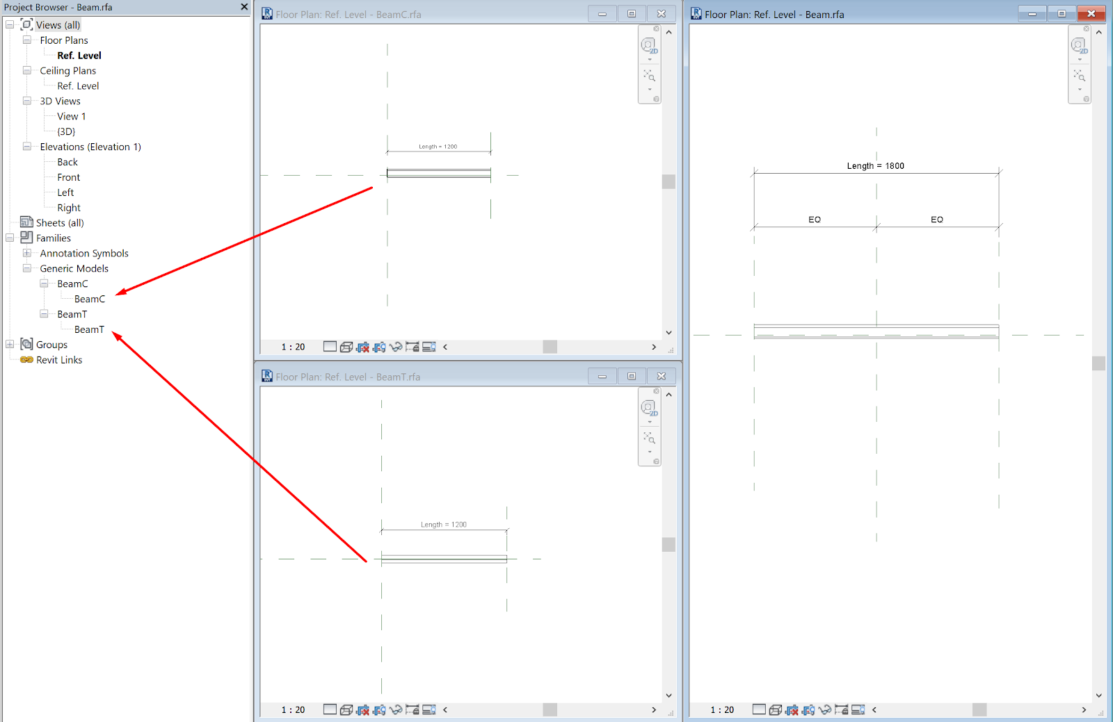
Using Family unit Type Parameters in Formulas
You can utilise family blazon parameters in formulas to, say, alter the shape of a axle when the length goes in a higher place a certain value. In the moving-picture show below, the 4 beams belong to the same family unit only the longer ones have a double T-shaped profile and the shorter ones have a C-shaped contour.

To achieve this behavior, create a beam using the Structural Framing template. Save it equally Axle.rfa.
Then create ii generic model, line based families with a sweep, one using a double T shaped profile (Beam T.rfa) and another using a C-shaped profile (Beam C.rfa)
Load both families in Beam.rfa. Place 1 instance of the Generic Model, line based family and constraint it to the driving reference planes.
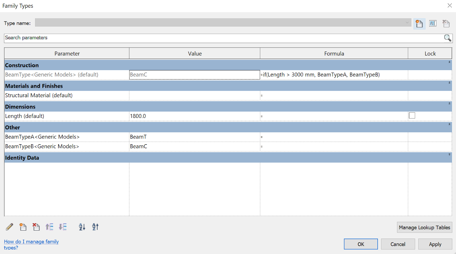
Now create three family type parameters. One (BeamType, instance) to drive the shape of the Generic Model case past assigning the label.

Two to hold the types for both options (BeamTypeA, BeamTypeB, blazon) and assign the formula every bit shown.
Bottom Line
Y'all cannot assign family unit type parameter to profiles directly. You must utilize a workaround creating generic model, line based families.
You lot cannot write types direct into formulas, but you tin create holding parameters to store the types of interest and reference them in your formulas.
2D Drawings
Detail Levels and Brandish in Views
Visibility of a family determines in which view the family displays and what information technology looks like in that view. Typically, when an chemical element is created by a family unit, the geometry of the element will change, depending on the current view. In a plan view, you may want to meet a 2d representation of the chemical element. In a 3D or elevation view, you may want a fully detailed 3D representation of the element. You have the flexibility to brandish dissimilar levels of geometry.
The visibility settings of each element in your Family can be customized to determine when they brandish. Conditions available include Plan/RCP, elevation views and Coarse, Medium and Fine detail levels. So. you can adjust the level of particular of each view (ix combinations).

Complete the Parameterization
Bank check that your Family has all the parameters you need to define information technology: sizes, materials, information elements, etc.
In add-on to deciding what the parameters need to be, you will besides need to consider whether they will need to exist used in schedules or tags, and whether they volition be type or instance parameters.
When creating a parameter, there are several items that you need to consider carefully:
Will the parameter need to be reported in a schedule or will it need to be part of an intelligent annotation tag? If so, it will need to be a shared parameter. Shared parameters are stored in an external text file so that they can be accessible to multiple projects.
What type of parameter is it? Length parameters are applied to dimensions. Material parameters can control the material assigned to a piece of model geometry. Yes/No parameters will provide a checkbox type of parameter. The parameter type is crucial to the behaviour of the parameter.
The parameter discipline volition command what types of units are available for the parameter.
Will the parameter be type-based or case-based?
Visibility Parameters
Revit has the ability to use if statements and (Yes/No) parameters to control the visualization of elements inside families. For example, we can plow off some elements when the width of the family unit is smaller than a specified size.
When selecting the elements we accept to click on the Graphics/Visible of the Properties window and Associate a Parameter.
The visibility parameters only work once the family has been either loaded into another family or loaded into a projection. Once the visibility parameter has been added to the family, we can apply an "if" statement to set the options based on a condition.
If (condition, truthful, false)

Complete all the Family Types
Consummate all the Family Types that you need. Complete all the types changing the value and information of the parameters created.
If you lot want to control the values of the family types parameters advisedly, you can simplify the process using Excel.
A type itemize lists all of the types in a family, allowing you lot to select and load only the types yous demand for the current project, resulting in a smaller project file size.
To create a type catalog, you create an external text file (TXT) that contains the parameters and parameter values that create the dissimilar types in a specific family. You place this file in the same location as the family file so that when you select to load the family, the type catalog displays.
The easiest mode to create a blazon catalog is to use the Export Family Types tool on an existing family unit. Using this tool, you create the base of operations type catalog and so modify the text file in a text editor.
The original document exported, may seem a mess just afterward irresolute some aspects in Excel we can read information technology properly and afterwards modify it.


You lot can define boosted parameters as needed, making sure to use the delimiter and syntax specified in Revit. And then, you have to place the file in the aforementioned location as the family unit file so that when y'all select to load the family, the type catalog displays.
Be careful when saving the file, select .csv blazon but proper name with .txt extension.

Tips & Tricks
- Automated Sketch Dimensions: Automatic sketch dimensions are turned off past default. Revit LT at present knows where each line of this geometry exists with respect to reference planes or other sketch lines. If we turn on the automated sketch dimensions, Revit volition testify all these dimensions. As you add locked dimensions, they supervene upon the automatic sketch dimensions, as shown. They merely display if there is at least 1 labeled dimension in the family unit.
- Create your formulas in Notepad++, specially if they contains nested IF statements. Revit formulas editor simply sucks: https://notepad-plus-plus.org/download/v7.5.1.html
- Angular dimensions usually crash when you work with pure angle values like 0º or 90º. You tin can use constrained revolves in order to get a better operation of your angle based objects.
- The all-time way to flex your family is to load information technology into the project.
Conclusion
In this guideline we have covered all the process of creating a family pointing out most advanced settings and possibilities that the families offer.
- Reference Planes (categorization).
- Angular Dimensions.
- Nested Families.
- Shared Parameters and Shared Families.
- If statements and Yes/No visibility parameters.
- Type Catalog.
- Automated Sketch Dimensions.
appletonrecithe1982.blogspot.com
Source: https://www.modelical.com/en/gdocs/complex-families/
0 Response to "How to Have Family Types With Different Number of Same Item"
Post a Comment